Lets go for an update on the #vengadores team project.. As you already know we have a rare triple R structure, in the pictures below we can see how we assigned our frames in the structure. We did it following the rules for the DH parameters. As we can see we have already make the DH parameters for 3 and for 6 DoF structures. After we´ve done that we can proceed to get the DGM for each structure. First we have to substitute in the Ai formula to get A1, A2, A3, A4, A5 and A6. In order to get the DGM for the 3 DoF structure we must multiply A1*A2*A3, and for the 6 DoF we must multiply A1*A2*A3*A4*A5*A6. Using Matlab we can solve the multiplications in an easiest way. After doing the multiplications we will have our 2 DGM for each one of the structures.
Continuing with the advances of the cartesian robot, the team presents its direct geometric model for the case of 3 degrees of freedom (DOF) and the case of 6DOF in the images shown below.
Diagram representation of a 3DOF cartesian robot
Placing all the reference frames according to the Denavit-Hartenberg parameters, we were able to get the following table:
For the 6DOF diagram, assuming that we have 3 additional rotation joints to set orientation to the robot. We would have the following representation:
For our robot motion RPR, we need joints that are able to rotate and others that are able to do translation, so for the rotation the best device that we can use is a servomotor and for the translation we can use an endless screw as well. Since our robot is gonna be getting its motion by using motors, the structure must be made out of a light material, and what we found is that the MDF is a light and easy to use material so we can use that to hold our structure and our motion devices.
One of the most important factors for the development of the project is the design, if it does not have a design referring to the shape and dimensions, we cannot make real measurements. After defining dimensions and prototypes we must decide the material based on its resistance, cost and ease to find a place where we can get the pieces. The possible materials are MDF, acrylic or 3D printing, any of the specific options due to the task of developing meets the resistance. The advantages of each are mentioned below. MDF laser: low cost, there are many shops dedicated to this. Acrylic: more resistant than MDF, being transparent can observe the structure and connections. 3D printing: great advantage to model pieces with more complex, resistant morphology. Given this we believe that the best option is to choose 3D printing and that the pieces are more solid and complex. To facilitate the design we will rely on projects that are already developed and functional. Although a robot does not meet our specifications it will be helpful to observe its development for us to reach our goal.
It is also important to identify the electrical and electronic components that will be used, it is more convenient that we use servomotors because the handling is easier compared to others. These Servomotors will be controlled by an arduino with a program already loaded and created by us, this in order to work properly.
The following image is a sample of how our motors could be connected to the arduino. In the same way we continue in the research process hoping to find the best solution and meet the expectations of the subject.
For the very first term, our team Engelberger Co developed a 3-D model prototype. This prototype represents the main purpose of our robot (carthesian coordinate robot), which as we can see, its three principal axes of control are linear (x, y, z). They move in a straight line rather than rotate.
Applications
CNC lathes production line for continuos parts loading and unloading.
Hello there! Team Fast & Furious here, presenting to you our assignment for Robotics class: the SCARA Robot.
This robot recieves it’s name by it’s achronim Selective Compliant Assembly Robot Arm or Selective Compliant Articulated Robot Arm. This is a three degrees of freedom robot, consisting of two rotational joints and a prismatic joint along the z axis (RRP). It is best known for it’s fast work cycles, as well as it’s great repetitiveness.
Knowing that the SCARA has many applications in the industry, we hope we can represent it’s functionality through this proyect, and we will be pleased to share the process with our readers.
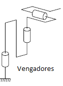
Hey everyone we’re #Vengadores and we’ll be making an (RRR) manipulator, our structure is like the combination of the regular ANTHOPOMORPHICAL manipulator (RRR) and the regular SCARA manipulator (RRP). We already discussed the design of our robot and the motors that we’ll be using. In the next 2 pictures you’ll be able to see the design and the structure of our manipulator.
An RPR robot is composed by a rotation, a prismatic movement, and another rotation(Figure 1).
Team Alpha’s robot
During the past week we gathered information about the mechanism that we will use and the materials we can use to make this robot.
We also settled with the motors we would use for the movement of the joints. The rotational movement will use a servomotor and for the prismatic movement we will use a stepper motor.
The #DreamTeam will be in charge of designing and building a 3 DOF RRP robot based on the kinematic diagram given by the profesor.
Figure 1. Kinematic Diagram.
Figure 2. RRP robot example.
An RRP robot counts with two rotational joints and a prismatic one, as seen on Figure 1, and because of the workspace it generates it is categorized as a spherical robot. Because of its kind of movement, this robot emulates up to a certain point the movement of a human arm.
During this week we started discussing possible materials and components to use for this project. For the rotation movements we decided to use servomotors because of the precision we can get through them, and a stepping motor for the prismatic movement, while for the control part we’re thinking on using an Arduino board and a motor shield. To build the structure and gears the possible materials are MDF and maybe acrylic.
Based on the project requirements we must follow the following kinematic diagram:
Figure 1. kinematic scheme
Figure 2. approximate prototype
The robot to be designed will be
anthropomorphic and will have four links (including the fixed link or earth)
and three degrees of freedom. Each of the degrees of freedom will be of the
rotational type.
It will
be sought that the manipulator is light but resistant, arguing with the team
and taking advice from more advanced classmates we have as possible materials
acrylic and mdf.
It is also important to
take into account a good selection of the components, such as the power supply
and the servomotors of this arm, since they must work properly and meet the
required expectations.