During this last term we found the singularities of our robot. We have an RPR robot which we already had the Jacobian matrix. So now, we focused on solving the singularities to know where our robot will not be able to generate any velocity; this was faster with Matlab. We know that singularities occur whenever the determinant of the Jacobian is equal to zero. Therefore, since our robot is a 3dof robot, we checked the determinant of the linear velocity of all 3 axis. The following was the determinant:
Figure 1. Determinant of the Jacobian in the linear velocity.
If we factorize and simplify, we get to the point in which we know, there will be a singularity when t3 is equal to zero or any multiples of pi. This means that when the robot is in home position, the end effector’s link won’t be able to generate velocity in the direction that it is pointing. It also has a singularity when it is at pi radians, however, the motor cannot go to that position, so that won’t be a problem in our robot.
There is another singularity in our robot when cos(t3)=-L1/L3. This singularity wouldn’t be a problem if L1 was larger than L3, which will make the cosine bigger than 1; this is not possible, so it would never occur. However, in our design, it’s the other way around; L3 is larger than L1. In our interface, we’ll have to be careful when than happens.
Due to some issues detected with the previous mechanical model, it has been decided that the structure of the robot will be changed; instead of building an PRR SCARA robot, the RRP was chosen. The problems we solve with this change are mostly mechanical and have to do with our motors’ capacity and torque, besides the fact that it will be easier to reach any point in the task space if we have the P joint at the end of the chain.
The design of our robot’s structure was made based on the task space we must achieve, which consists in a 20 cm3 cube. Considering that our robot has an RRP structure, we will have a total of 2 links.
For practical purposes, the lengths for links 1 and 2 were proposed as 35 cm and 30 cm, respectively, as shown in figure 1. Based on this, we developed de DGM od this model, detailed further in this document, with which we were able to find the IGM for a desired position of the end effector in the task space. This way, we proved that the lengths were suitable for this project.
New mechanical design of our RRP robot. Isometric view of our robot.
In order to control the Cartesian robot, the Engelberger Co. team developed a human machine interface(HMI), which is shown below.
Figure 1 .- Developed HMI
The interface communicates with the arduino through the serial port, and the operation process begins as follows:
The Arduino program remains on a “stand-by” mode until some data is received by the serial port, then the HIM opens the port and if connection is successful, it will send a data frame , which have this structure :
data #1 = Manual mode /Automatic mode
data #2 = Coordinate X
data #3 = Coordinate Y
data #4 = Coordinate Z
data #5 = Gripper
It was possible to perform tests using the manual mode to control the motors assembled in the robot with the information previously given.
As we mentioned in some previous posts, we have developed the mechanical structure of our robot. A 3D model of this structure can be seen in the following image.
Figure 1 – 3D Model Cartesian Robot
Once the material was bought by the team, we were able to finish the mechanical work. The next photos will show the state of our cartesian robot structure.
Figure 2 – Cartesian Robot, mechanical work – Photo 1
Figure 3 – Cartesian Robot, mechanical work – Photo 2
Electrical work
The following circuit represents the physical connections in the robot assembly.
Figure 4 – Electrical connections
Pulses will be sent through the Arduino digital output
ports to the A4988 controllers in order to control the stepper motors, which
will have the required configuration at the time of programming.
To finish with this blog post, we would like to mention that we have already arrived to make some tests in order to control the robot motors. Here we have an example where the three motors were moved at the same time with the same speed.
In comparison with the previous mechanical design, we make some modification for the pieces, we already sent to the laser cutter in MDF of 3mm so, figure 1 shows the pieces that we used to build the robot structure.
Figure 1
However, with this structure, we verified how long the arm reach for each position, unfortunately, doesn’t reach the 20x20x20 cm space working, so, we have to re-design our model for the robot, transforming the second joint which is connected to the gripper, in two joints, this way we can reach the 20x20x20 cm space.
1st Configuration
We already talked about the modification of some pieces that make the skeleton of our robot, therefore, we design the pieces of the figure 2, those pieces belong to the base and the floating arm of the robot, which is the one that is connected to the tool. Also, we decided to use some of the pieces that we had before.
Figure 2
In figure 3 there are three circles in the base, the first one is to make the base firm and avoiding unexpected vibrations, the second one, is the base of the first servomotor (it has a rectangular gap as well), and the third one is connected with the first arm of our robot, so that means that circle is the base that is spinning around the axis of the servomotor on the second circle.
Figure 3. 2nd Configuration
For now, we are going to keep this mechanical configuration, of course if this design doesn’t work to make the fluid motion, and in the case that some singularities unfortunately affect the principal task, we will change it.
IGM SOLVED
DH PARAMETERS
GRAPHICAL INTERFACE
3 DOF GRAPHICAL INTERFACE
6DOF GRAPHICAL INTERFACE
CONCLUSION
To sum up all the things that we mentioned in the last advance and this one, we have controversies, with the mechanical part, because, in the first advance we wrote that the mechanical design will be composed by only two joints, however, at the moment that we built the robot, unfortunately the results wasn’t the ideals for us, and the mechanism didn’t reach the 20x20x20 cm workspace, and we decided to make some changes for the joints, and convert one joint in two.
Also, we are still considering the servomotors that we’re going to use, because the weight of the tool, was heavier that we were expecting, and if the one’s that we were considering on the previous advance doesn’t lift that weight in a fluent form, we’ll have to change them for ones with more power.
Making all the simulations and programs to solve the exercises of DGM and IGM, help us to realize the form of the movement of the joints more easily, and give us the results and configurations for the program parameters that we’ll have to send them to control the servomotors of our joints.
In order to compute the torque needed to pick up a 200g body, we know that we have three screws allowing us to move in the three coordinates frames, perhaps we are using a steel rod as a guide in the X axis to assure the correct displacement.
We are developing the calculations for the screw in the x axis, because this is the one who is supporting a larger weight. (It supports the Y and Z axis)
From the book “Shigley´s Mechanical engineering design” in chapter 8 “Screws, fasteners, and the design of Nonpermanent joints”, we get the formula allowing us to compute the torque needed by the screw to move the weight to which it is subjected.
Where,
Tr = Torque.
F = Force on the screw.
dm = Pitch diameter.
f = Friction .
l = Lap advance.
The pitch diameter is computed by the next equation:
The lap advance is the same as the pitch of the screw, which
means 4mm by revolution.
The friction coefficient is gotten from table 8-5 in the same book, the value is 0.17 since we have a brass flange.
Table 8-5 Coefficients of friction “f” for threaded pairs.
To get the force on the screw we add the weights of the structure supporting the x axis (2 aluminum profiles and 4 guides), and the weight of the body to pick up.
The weight of the aluminum profiles is 0.9 kg/m, we have two profiles of .24 each, then a total weight of 0.432 kg. Further, each guide has a weight of 2.44g, for a total of 9.76g. The gripper has a mass of 40g. For a total weight of 0.48176 kg.
Thus:
Calculating torque, we get:
Since the stepper motors we chose provide us with a torque of 0.4 Nm we can confirm that we are going to be able to pick up a 200g body.
The construction and design of a robot implies a lot of topics that we have seen in the career like Mechanical design, Cinematics, Microcontrollers, Control, Motors and circuits. Its fundamental to know how to apply these knowledges.
MECHANICAL DESIGN
The preliminary mechanical structure was made in Solid works to give us an idea how we are going to build the robot.
ELECTRICAL DESIGN
For the rotational links we are going to use servo motors that are going to be controlled with an Arduino UNO because it already has a library for servo motors that makes easier the manipulation of the robots.
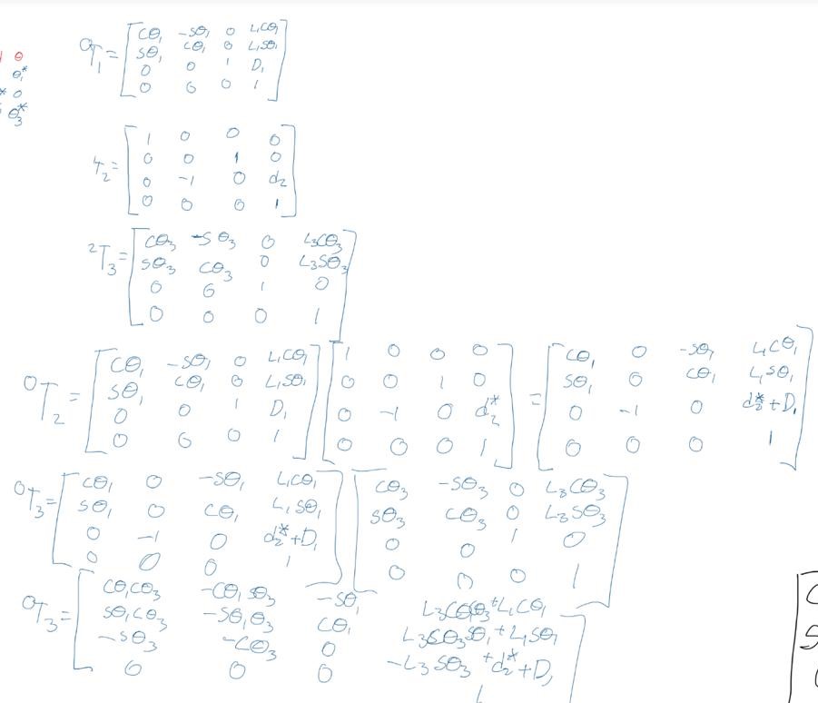
Last week we obtained the DGM of the robotic arms of 3 and 6 DOF, applying the Denavit-Hartenverg method, for the i to j transformations (0 to 3 and 0 to 6), where the first 2 matrices of both cases remained the same:
DGM:
Mechanical Design
We used solidworks to design our concept, getting an initial idea like the following:
Whose individual parts are shown below:
After some modifications the design changed as follows. With the dimensions shown in the drawing.
Electrical design
For our circuit design, we decided to use arduino as the controller, we also chose mg995 servomotors for rotational motion, because we found that it can be used for continuous motion and has the torque we believe necessary. Also we will use a stepper motor with a rack and pinion for prismatic motion.
For the elaboration of this project we had two ideas to build the RPR robot arm, each one has its own restrictions and limitations, but they were thought to accomplish the requirements, both of them use the same electrical design and probably the same number of motors
these probably won’t be the final designs, since many considerations still have to be taken, such as the weight of the material, supports, bases, and positioning of the mechanical and electrical elements.
The first idea, is so far the most complete since it allows a better positioning in space, as well as spaces for mechanical accessories. With this sketch, the robot can reach to touch any point of a 20x20x20 cube in space
Electrical design
This will be the connection of the motors that will give the movement to the robot, the controller as observed will be an Arduino Uno. The two servomotors will be the ones that give the rotational movements in the base and the tool, and the stepper motor coupled to an endless screw, will give the prismatic movement
**The power sources, transistors, and any other components that are required will be added as the connection is made or needed
DGM – 3DOF
After obtaining the table, it will be resolved with Matlab using the previous parameters.
we obtain the matrix
with the end-effectors position and orientation with respect to the base.
Proposing D2=12 cm, Θ1=π/4 and Θ3=π/4, we get the following
matrix and graph
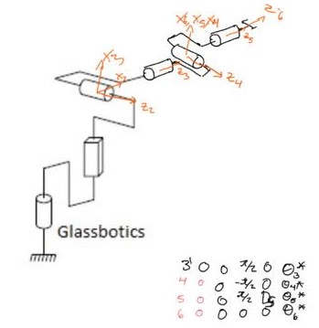
DGM-6DOF
adding
a spherical joint at the end of our robot we get a 6DOF robot which we analyze
here.
Using the same function in Matlab we get the following result:
For our robot’s mechanical model, we have considered to build a structure out of MDF wood, with different thicknesses for different parts of the structure.
The next figure shows our proposal for the building of our robot, with approximate dimensions, considering that the end effector has to be able to reach any point inside a cube with dimensions 20x20x20. This model is not definitive, due to changes that can come up in the process of building and perfecting our robot.
Electrical design
For our robot’s electrical design, we propose to control it with
an AVR ATmega328p microcontroller.
We have considered to use servomotors for Rotative joints, and a step motor with an endless screw for the Prismatic joint.
This model was created on the software Proteus.
3 dof prototype Direct Geometric Model
This is the solution of Direct Geometric Model using the Denavit- Hartenberg method, above is the table of the DH parameters that the method use. Under is the solution with the product of each transformation, that give us the end effector’s position and orientation with respect to the base frame.
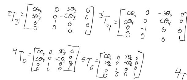
6 dof Direct Geometric Model
This is the solution of Direct Geometric
Model using the Denavit- Hartenberg method, above is the table of the DH
parameters that the method use.
Under is the solution with the product of
each transformation, that give us the end effector’s position and orientation
with respect to the base frame.
As we can see, the solution using the matrices is just using the transformations of R3 to R6, because the first part of the robot (R0 to R3) was previously demonstrated.
Now, we use the matrix and the matrix to obtain the matrix that give us the end effector’s position and orientation with respect to the base frame.